admin@hepacleanroomfilter.com
AC FFUs use a manual speed control system suitable for facilities with fewer than 200 FFUs. In contrast, EC FFUs are ideal for large cleanroom facilities, They employ intelligent control systems managed by computers for each FFU, resulting in improved efficiency and reduced maintenance costs.
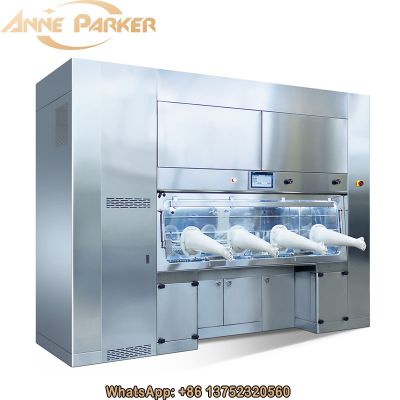
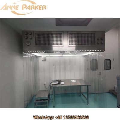
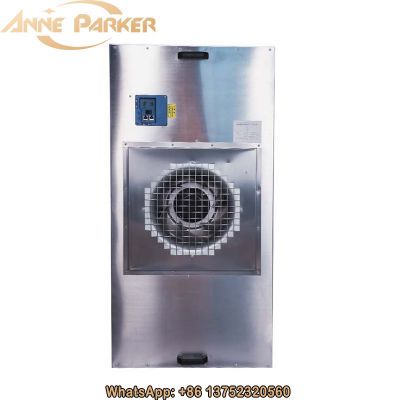
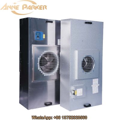
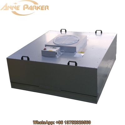
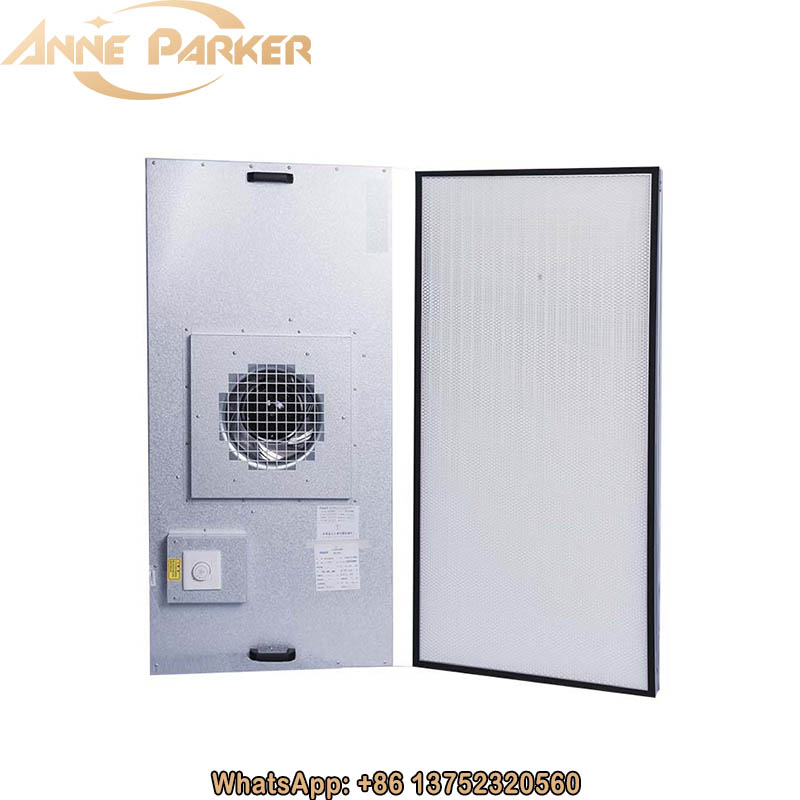
FFU Clean Room HEPA Fan Filter Unit Specifications Design
More energy-efficient
EC FFUs can save about 30%-40% energy compared to AC fan FFUs.
Quieter operation
EC FFUs are about 5 dBA quieter than AC fan FFUs.
Easier control
AC FFUs use a manual speed control system suitable for facilities with fewer than 200 FFUs. In contrast, EC FFUs are ideal for large cleanroom facilities, They employ intelligent control systems managed by computers for each FFU, resulting in improved efficiency and reduced maintenance costs.
As customer demands for energy efficiency, noise, and controllability of FFUs increase, the application of EC FFUs is becoming increasingly widespread. In the following section, we will introduce the performance and technical features of EC FFUs, focusing on the fan, filter, housing, and control system.
Technical advantages of EC FFU

Active PFC technology

EBM fans can save energy up to 33%, while passive filtering method can only save 4%.
Compensation principle
Active power filters generate harmonic currents with equal amplitude but opposite phase.
This ensures that the load current on the supply side is a sine wave.
Main hazards of harmonics
Harmonics can cause relay protection and safety automation devices to fail or malfunction.
They can trigger resonance phenomena, which may result in damage to capacitors and transformers due to overcurrent or overvoltage.
Harmonics increase the harmonic losses in power systems.
They diminish the efficiency of electrical equipment, causing devices like rotating motors, capacitors, transformers, and conductors (e.g., low-voltage neutral lines, cables, bus bars, etc.) to operate under overload conditions (heating, vibration, abnormal noise, etc.), thereby shortening their lifespan.
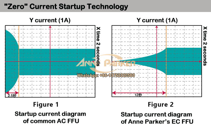
Figure 1 depicts the startup current diagram of typical AC FFUs and some domestic DC FFUs. Within 2.5 seconds after startup, a significant inrush current is generated, which is usually 3.5 times of the running current. This surge exerts a considerable impact on the power grid and power switching system.
Anne Parker EC FFU adopts German EBM fan, incorporating a gradual current discharge function. Upon FFU startup, the current gradually increases over 12 seconds before reaching the running current level. This feature effectively safeguards the power grid and power switch systems.
200V-270V ultra-wide voltage design
After 2004, DC fans integrated rectification and communication modules within the fan, effectively becoming a single unit. This change introduced the wide voltage design concept.
Voltage fluctuations are common in large electronic factories, where the start and stop of large electrical equipment such as air conditioners, pumps, and boilers can cause voltage fluctuations. The 200-270V wide voltage range ensures stable operation of the fans despite grid voltage fluctuations.